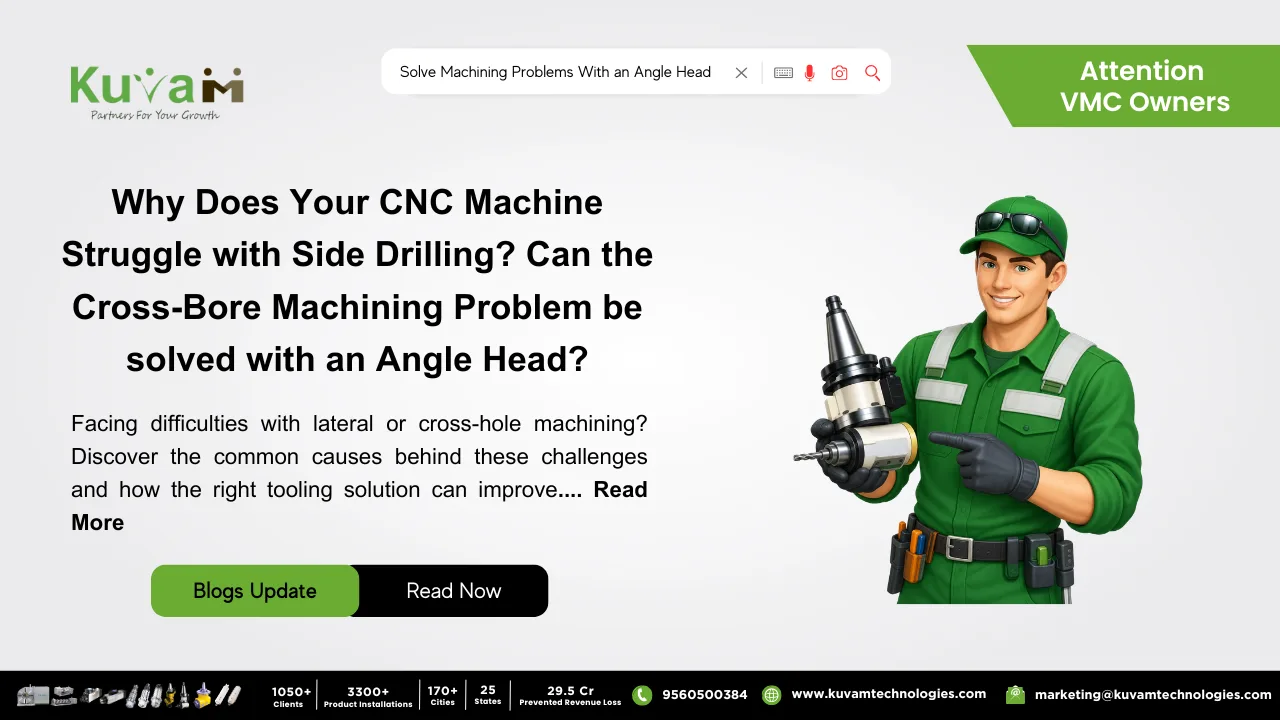

Angle Head is a very useful tool for side machining. When side-entry holes, cross-bores, and lateral slots force your team into a second machine setup — adding cost, time, and tolerance risk an Angle Head is the precision attachment that removes the problem entirely.
There is a moment in every machine shop that signals a deeper problem. The part comes off the primary operation looking exactly right faces milled, bores drilled, the main geometry complete. Then the drawing is checked again, and the reminder arrives: there are cross-holes to drill on the side face. Or a lateral slot that runs perpendicular to the spindle axis. Or a set of threaded ports that approach at 90 degrees to the orientation the machine was set up for.
What follows is the sequence that costs machine shops more time and money than almost any other single production pattern: unclamp the part, re-orient it, re-fixture it, re-indicate to a new datum, run verification cuts, and finally start the lateral operations before doing it all again if there is a third or fourth face to address. For a batch of fifty components, this overhead does not just add minutes per part. It adds hours to the schedule, uncertainty to the tolerances, and real margin erosion to work that looked straightforward on the quote.
The solution is not a new machine. It is an Angle Head for VMC milling a precision attachment that redirects your existing spindle’s power to a perpendicular output, enabling lateral and cross-bore features to be machined in the same setup, on the same machine, without unclamping the part.
Why Lateral Features Create Disproportionate Production Cost
The problem with lateral and cross-bore features is not that they are difficult to machine. The operations themselves drilling a cross-hole, milling a lateral slot, tapping a side port are straightforward. The cost is entirely in the repositioning that conventional setups require to reach them. Every re-clamping operation carries overhead: time to unclamp, time to re-orient, time to indicate to the new datum, and time to verify before cutting. For a component with lateral features on two faces, this overhead happens twice per part.
⚠️ THE HIDDEN COST OF MULTI-SETUP LATERAL MACHINING: In a typical machining cell, re-clamping a component to access lateral features adds between 15 and 35 minutes of non-cutting overhead per part. On a batch of 100 components requiring two re-orientations each, that represents 50–115 hours of pure setup overhead time that does not appear in the cutting cycle but determines whether the job is profitable or not.
There is also a quality dimension to this problem that production reports rarely capture directly. Each re-clamping shifts the workpiece datum. Lateral features machined in a second setup do not share the same positional reference as the primary features they share the reference established at the second clamping. Any error in that second setup translates into a positional relationship error between primary and lateral features that the customer’s inspection process will find. Angle Heads eliminate the second clamping. And with it, the positional risk between feature sets.
An Angle Head does not change the cutting tool or the material or the machine. It changes the geometry of the setup and in doing so, it turns a two-operation job into a single-operation job, on the machine you already own, with the tooling you already use.
What an Angle Head Is and How It Works on Your Existing Machine
An Angle Head is a compact, precision-engineered attachment that fits into your machine’s existing spindle interface the same tool holder connection used by your existing cutters. Inside the body, a precision bevel or miter gear set receives the rotational power from the spindle and redirects it to a secondary output spindle oriented at the required angle most commonly 90°, though adjustable and multi-angle variants provide flexibility for non-perpendicular features.
An anti-rotation lug on the body of the Angle Head engages a reference point on the machine’s spindle head or a dedicated fixture, preventing the body from spinning while allowing the internal gears to transmit torque cleanly to the output. The output spindle accepts standard tooling end mills, drills, taps, and boring bars through a standard collet or tool holder interface. Coolant can be directed through many models. The cutting forces are supported rigidly by the body, and the assembly is engineered to maintain output runout within production-grade tolerances typically under 0.005 mm TIR on precision models.
Angle Head Types — Matched to the Operation
| Type | Output Angle | Best For | Key Advantage |
| Fixed 90° Angle Head | 90° perpendicular | High-volume production where lateral features are always perpendicular | Maximum rigidity; highest output accuracy; lowest runout |
| Adjustable Angle Head | Variable (0°–180°) | Job shops handling varied angular feature requirements | One attachment handles multiple output angles without changing units |
| Compact / Stub Angle Head | 90° in reduced envelope | Deep pockets, confined cavities, or tight clearance machining | Short nose-to-tip distance reaches features standard heads cannot access |
| Multi-Spindle Angle Head | Multiple 90° outputs | Production components requiring several lateral holes simultaneously | Multiple features in one pass dramatically reduces cycle time |
What Manufacturers Actually Gain When an Angle Head Enters the Workflow
| 1 Setup for primary and lateral features combined | 50%+ Reduction in setup time on multi-face components | 0.005mm TIR output runout on precision Angle Head models | Zero New machines required — mounts on existing spindle interface |
Key Benefits of Using an Angle Head
| ✓ Lateral features without re-clamping — Cross-holes, side ports, and lateral slots machined in the same setup as primary operations one datum, one clamping, zero re-indication |
| ✓ Improved inter-feature positional accuracy — All features share a single datum reference; the positional relationship between primary and lateral features is governed by machine accuracy, not re-clamping consistency |
| ✓ No machine upgrade required — Mounts on any standard spindle interface (HSK, BT, CAT, ISO); compatible with 3-axis, 4-axis, and 5-axis machining centres |
| ✓ Standard tooling compatibility — Accepts existing end mills, drills, taps, and boring bars; no new tooling investment beyond the attachment itself |
| ✓ Angle Head vs 5-axis machine — For the specific problem of 90° lateral features, an Angle Head delivers equivalent positional results at a fraction of five-axis machine investment |
Which Industries and Applications Benefit Most from Angle Heads?
| Aerospace & Defence Hydraulic manifolds, actuator housings, and structural brackets with cross-bores and lateral port features that must maintain tight positional tolerances relative to primary geometry. | Automotive & Engine Components Engine blocks, gearbox housings, and brake components with oil drillings, cross-shaft bores, and lateral threaded ports all reachable in a single setup with the right Angle Head. |
| Medical Device Manufacturing Surgical instruments and implant components with cross-bores and lateral features where dimensional consistency and traceability across a single clamping are regulatory requirements. | General Engineering & Job Shops Any component with features on more than one axis of approach flanges, valve bodies, pump housings — where re-clamping overhead is the main barrier to competitive pricing. |
| The components that need lateral features are not the hard jobs. The hard part is the re-clamping between them and an Angle Head is how that hard part disappears. One attachment. One setup. Every feature complete. On the machine you already have. |