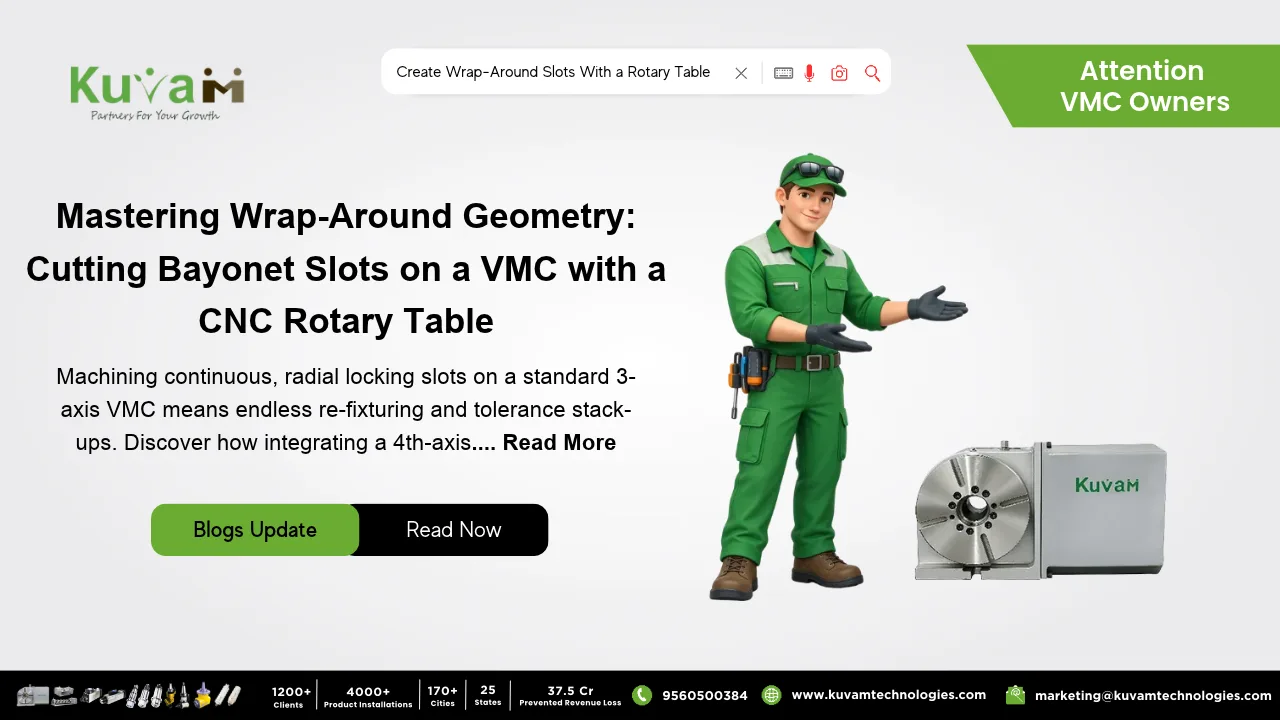

A Rotary Table is the best all-rounder tool for machining. It is especially useful for creating curved slots, Bayonet slots, J-slots and windows on round components such as connectors, lens, barrels, hose couplings, and locking mechanisms.
When a slot needs to curve around the outer part of a cylindrical surface, a normal 3-axis VMC can easily machine the top surface but is unable to reach around. That is where the Rotary Table comes in.
Why Wrap-Around Slots are a Problem on a Three-Axis VMC
A VMC moves the cutting tool in three directions: X, Y, and Z. Machining a flat surface is easy because the cutter works on one plane, and G02 and G03 commands help create curved slots. On a cylinder, the surface curves away from the cutter, and the slot has to follow that curve. If you try to cut it with only linear axes, the slot depth changes as the surface falls away, the walls tilt, and the width stops being consistent.
Without a rotary table, shops usually have three options. They can cut the slot in sections and manually rotate the part between cuts, but this requires multiple setups and can leave visible marks where the cuts meet. They send the part to a lathe with live tooling, if they have one or know somebody who does. Or they build a dedicated fixture for each tube diameter. All of it costs time, and none of it repeats well.
What a CNC Rotary Table Does Here
A CNC Rotary Table is a precision device that mounts on the VMC table and gives the machine a fourth axis, usually called A. It rotates the part around a fixed axis under a controlled program, so rotation becomes another move alongside X, Y and Z. For a tube, the table is set up so the tube’s axis runs along X, held in a chuck, with a tailstock or a plug at the far end for support.
By combining the rotary movement with the machine’s X, Y, and Z movements, the operator can create different slot shapes, including circular, J-shaped, and bayonet slots. This reduces manual work, avoids repeated setups, and produces more consistent results.
The Numbers
The slot width is the cutter diameter, so a 1/4 inch end mill cuts a 1/4 inch slot. The slot depth is set by Z, measured from the tube’s top surface.
The length of the slot around the surface depends on the tube’s diameter and the angle you rotate. On a 2 inch outside diameter tube, 60 degrees of rotation covers about 1.05 inches of surface (pi times 2, times 60 over 360). A bayonet slot might have a half inch axial entry, a 60 degree sweep, and a short axial return to form a detent. In the program that’s one X move, one A move and a final X move.
Your CAM software handles this with a wrap toolpath, which unrolls the cylinder into a flat sketch and converts it to X and A moves. You draw the slot as it would look flat, and the software does the rest.
Setting It Up
Hold the tube in a chuck on the rotary table, with the axis of rotation lined up with the machine’s X axis. Indicate it along its length so it runs true, because any runout shows up as a slot that gets deeper and shallower as the part turns. Support the far end with a tailstock if the part is long. For thin-wall tubes, a plug inside the tube keeps the jaws from squeezing it out of round.
Touch off the top of the tube for Z zero. Set the A axis zero on the Rotary Table where the slot begins.
Rotary feeds trip up a lot of people. The control reads feed on the A axis in degrees per minute, and the surface speed changes with diameter. Most CAM packages calculate it for you, but check the feed on a test run before cutting the real part.
Where Else This Shows Up
Wrap-around features become more common, once you start looking for them: twist-lock caps, quick-connect fittings, lens mounts, spiral retaining slots on handles. Because the whole slot lives in one program, part fifty comes out matching part one, and a change in slot length is an edit to a single number.
What Can Go Wrong
Runout is the main reason. A wobbly tube gives a slot with uneven depth. Chips can gather into a narrow slot, so use air or through-coolant and clear them. Tool deflection can bend the walls, so take a roughing pass and a light finishing pass. It is also very important to check the clearances in the simulation, since the chuck, tailstock and rotary table can all reach the spindle or the cutter path as the part turns.
Is it Worth Adding One?
If your VMC makes parts with slots, windows or grooves around cylindrical surfaces, even a few times a year, a CNC rotary table pays for itself by removing the extra setups and fixtures. Pick one with enough load rating for your longest tube, confirm the control has a fourth axis option, and make sure your CAM software can post for it. With those in place, the job runs as one setup, start to finish.